Written by Viktor P. Astakhov
Edited by Mort McClennan
Hyper Tool Company
Gundrilling precision cannot be defined in exact formulas. Effective systems combine practical experience with process theory to solve difficult application problems.
Gundrills produce first-pass, high-finish, straight holes of varying depths and diameters in a wide variety of materials used in the automotive, mold and die, aerospace, firearms, medical, power and other industries. They work best when the combined cutting speed (rpm), feed, tool geometry, carbide grade, and coolant parameters properly match the work material hardness, composition and structure, the deep-hole machine conditions, and required hole quality.
Process efficiency is measured by the cost per unit length of drilled holes. Every system component – the gundrill, machine and controls, fixture and accessories, workpiece, operator, and maintenance – affects efficiency. For example, the same gundrill used in different machines may either break or work effectively. One gundrill used on the same machine works differently on separate materials. The coolant brand, coolant flow rate, filtration and temperature can each cause one gundrill on one machine to perform differently on the same material. Operator experience and training plays a key role in every situation.
Gundrilling precision cannot be defined in exact formulas. Effective systems combine practical experience with process theory in four specific areas to solve difficult application problems:
The Gundrilling Method
First, analyze the machined-hole quality requirements. Three characteristics are usually most important deviation (drift) of the hole axis, surface finish, and diametric accuracy. The part drawing defines the one or two most important criteria used in selecting one of the three gundrilling methods in terms of relative rotation, as shown in Figure 1 (click image for larger version):
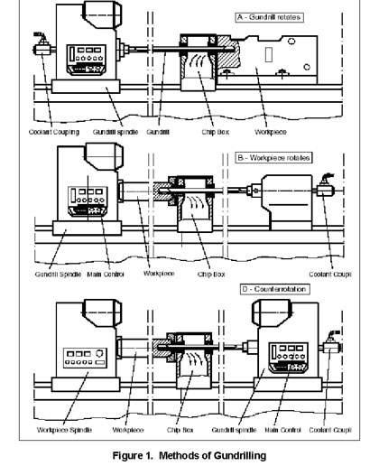
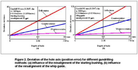
Rotate the gundrill and hold the workpiece stationary . Use this approach when the workpiece shape is not suitable for rotating. Gundrill accuracy and the gundrilling installation are crucial here. Gundrill component alignment must be almost perfect when drilling hole diameters smaller than 10mm in light materials such as aluminum alloys, where the 6,000-15,000 rpm cutting speed and the 600-1000 mm/min feed rate are high. The best diametric accuracy and surface finish, along with worse axis deviation of the machined hole, are common in this method. When hole axis deviation is important, focus on the feed motion accuracy and clearance in the starting bushing, drill holder-starting bushing and whip guide alignments. Be aware that the whip guide alignment affects hole axis deviation much more than the starting bushing, as shown in Figure 2 (click image for larger version):
Rotate the workpiece and hold the gundrill stationary . Use this method when the workpiece shape allows for accurate clamping and high-speed rotation. It simplifies drill monitoring, coolant supply and chip evacuation. Minimum hole axis deviation and worse diametric accuracy are common features. When diametric accuracy is also important, keep the drill holder-starting bushing and whip guide misalignments to a minimum.
Rotate both the workpiece and the gundrill . This approach is sometimes called counter-rotation drilling because the rotations are typically opposite each other. Use this method when gundrilling small diameters, where one rotation speed cannot achieve the necessary cutting speed. Though long and expensive special machines having two spindle heads are required, this method must be used when the hole axis position and diametric accuracy are equally important.
Overall Drill Length
Overall drill length, determined by the tool layout' shown in Figure 3 (click image for larger version), is very important. Start with the length of the machined hole, add the four approach and overshoot distances, then add the bushing length including the bushing holder, chip box, etc.
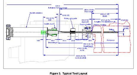
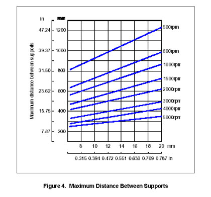
Now decide whether to use whip guide(s) from the data in Figure 4 (click image for larger version). Gundrills are classified according to their length of the shank-to-diameter ratio. A ratio less than 10 is short, between 11-50 is normal, between 51-100 is long, while ratios exceeding 100 require extra-long gundrills. If the shank length of an 8 mm drill rotating 3000 rpm is 400mm, then a whip guide is necessary because the maximum distance between supports is 350mm.
Adjust the gundrill system properties based upon the gundrill category being used:
Short gundrills . The key parameter is drill holder-starting bushing alignment, because a short gundrill shank is rigid and causes significant additional force proportional to the misalignment. This force may well exceed the cutting force and cause multiple drilling problems such as chipping of the cutting edge, poor surface finish, inadequate diametric accuracy, and reduced tool life. Misalignment should not exceed 2 microns. When this accuracy cannot be achieved, the gundrill length must be deliberately increased so the gundrill will self-pilot and avoid problems.
Normal length gundrills. The drill holder-starting bushing alignment must be adjusted no worse than 4 microns. This is crucial when the drill rotates because the additional force from misalignment causes alternating bending stress in the shank. The shank fails due to accumulated fatigue. This unpredictable failure occurs without any obvious warning.
Long and extremely long gundrills suffer low torsion strength. For a given drilling torque, the twist angle of the shank is proportional to its length. The maximum twist angle is located at the shank-driver connection. The shank fails when this angle exceeds its critical value, and the gundrill resembles a twist drill with a helical V- flute. A gundrill shank must be constructed from a high-yield strength material, with heat treatment transforming it to a tempered martensite structure.
Check your supplier on the gundrill content. High-yield strength materials present problems when the V-flute is crimped, so tubular 4130 steel products are common in gundrilling. Many gundrill manufacturers also do not have sufficient length furnaces and metallography equipment for proper heat treating. When the shank is brazed to the driver, excessive heat from brazing can anneal the tube in the area adjacent to the driver, where its strength is most needed. A shank made of high-yield strength material, properly heat-treated and properly connected to the driver, using a low-temperature brazing filler, can increase the gundrill's penetration rate twice that of common gundrills.
The drill holder-starting bushing alignment is insignificant when using extremely long gundrills. Clearance between the gundrill tip and the starting bushing is important and should ideally be next to zero. Achieving zero clearance in the starting bushing is not practical due to free penetration, tip back taper, and wear of the starting bushing. When the rotational speed and feed rates are high, as in drilling aluminum automotive engine heads, excessive clearance in the starting bushing is the main reason for entrance instability. Entrance instability is the prime cause of unpredicted drill failure. Use only a specialized gundrill bushing, check the clearance in the starting bushing periodically, and change the starting bushing when this clearance exceeds the clearance corresponding to ISO fit H9/h9.
The Coolant System
High-pressure coolant delivery cools the workpiece and the tool, lubricates between the tool and workpiece by reducing weld action and built-up edge formation on the cutting and supporting areas, and carries chips away from the cutting area along the flute to the chip box. Cooling action dissipates both the external friction heat and the internal deformation heat. The coolant must sufficiently combine viscosity and velocity to effectively remove chips away. An improper combination causes chip packing in the flute, leading to increased torque and probable drill breakage. Available coolants fall into three categories:
Straight Oils are generally recommended over water soluble oils for gundrilling. They significantly reduce tool wear, yield better surface finishes, and generally improve drilling accuracy. They should contain extreme pressure (EP) additives of 2.5-3.5% Sulphur for high-alloy steels and heat-treated cast irons, 3.5-5% Chlorine for light ferrous materials, and 10-14% of fat. Low viscosity (SSU) facilitates heat dissipation and load carrying capacity, reduces the risk of pump starving when cold starting, improves filter efficiency, and reduces the amount of oil carried off with chips. The kinematic viscosity should not exceed 20-30 cSt/20 o C. 45 cSt/20 o C can be used in exceptional cases.
Water Soluble Oils are more economical and can be used for non-ferrous metals and highly machinable steels under light cutting conditions. They are not recommended for tougher steels. EP additives help prevent material welding to the tip (BUE) and should contain film strength enhancers (animal and vegetable fats) to reduce friction and wear. Concentrations of less than 10% reduce film strength and create vapor pockets at high tool-load areas.
Synthetics are water-based fluids that are easier on the environment but harder on the gundrill. These should not be used in deep holes because they lack the necessary film strength.
Coolant filtration is essential because the coolant collects and circulates considerable quantities of both coarse and fine chips and must be purified for both tool life and hole quality. Poor filtration can increase coolant temperatures and result in rapid failure of the coolant pump. It causes premature failure of solenoid valves, leaking servo valves, and bearing failure in the rotating coupling. Generally speaking, use cartridge filters that separate particles in the range of 5-10 microns for high precision holes where surface finish is critical, 15-20 microns for precision holes, and 20-30 microns for normal holes. Cast iron drilling requires rough filters, magnetic drums or rolled media, followed by a bag-type or woven-media polishing filter.
The coolant temperature defines, to a large extent, its cooling, lubricating, and transportation abilities. This is crucial with oil-based active coolants. About 100 o F to 120 o F is generally recommended as the maximum coolant temperature. It can often be maintained by circulation through a heat exchanger or even by installing a fan to blow across the surface of the coolant reservoir. When drilling precision holes, refrigeration systems may be necessary.
The coolant pump . Specify a system using fixed-displacement pumps for best results. Most coolant supply systems still use variable-displacement pumps designed to maintain set pressure. If the coolant flow encounters an obstruction, the set pressure seen on the gauge by the operator will be maintained but the flow rate supplied to the tool will actually decrease because coolant is diverted through the pump's internal relief valve. An obstruction such as a chip jam in the flute of the tool can worsen and quickly lead to drill failure.
Coolant flow rate and pressure are important. The flow rate is the more important factor because it transports the chip along the V-flute. The coolant velocity in the V-flute in gundrilling is determined as the coolant flow rate times the channel cross-sectional area. For a given tool, the flow rate which assures the critical velocity is called the critical flow rate. The rule of thumb here is to deliver the sufficient flow rate, which is 20% higher than the critical flow rate. A flow rate less than critical makes proper chip transportation impossible, resulting in a chip plug in the V-flute that causes excessive drilling torque and usually breaks the drill. This common failure appears differently depending on whether the tip or tip-shank joint fails. If the shank is the weakest link, the excessive drilling torque twists the shank.
The coolant inlet pressure must be high enough to deliver the sufficient flow rate. Pressure may vary widely up to two times based upon the design of the gundrilling system. The critical parameters are the coolant viscosity, gundrill length, cross-sectional area of the coolant passage in the shank (various manufacturers use different tube wall thickness to produce shanks of the same drill diameter), the cross-sectional area and the coolant hole shape (whether one or two round holes, a kidney-shaped hole, etc.) in the drill tip point grind.
Only sufficient inlet pressure assures proper coolant flow rate. This may present a problem for gundrills less than 4mm diameter because many existing coolant delivery system are capable of generating only 1,500 psi coolant pressure. A coolant booster can be easily installed on existing delivery systems to supply up to 3,000 psi high-pressure coolant at a fraction of the cost of a new high-pressure system.
Process Controls
Select the minimum number of machine control inputs and outputs necessary to display all possible normal and abnormal situations within the gundrilling system. This reduces the initial launch cost and routine maintenance costs of the gundrilling system. There are two common mistakes to avoid:
First, never use amperage variation of the drive motor to measure the gundrill load. The gundrill and drive motor are installed on opposite ends of the spindle unit. The amount to which the gundrilling process contributes to the measured signal becomes insignificant compared to inputs from other drive train members rotating at high speeds such as the spindle, bearings, pulleys, drive motor rotor, etc. The situation worsens when the gundrill diameter decreases and the RPM increases.
Second, never convert' controlled inlet coolant pressure into the flow rate. Always directly measure the flow rate. If the coolant flow encounters an obstruction such as the braze filler partially covering the coolant passage in the gundrill and inlet pressure is kept the same by the control system, the actual flow rate decreases and may lead to reduced tool life, poor chip removal and even gundrill breakage. The same situation occurs when a chip plug forms in the V-flute.
Advanced systems focused on high-speed gundrilling must control the axial force, drilling torque, coolant inlet pressure and flow rate, chip flow rate and the system frequency. An expert system within the controls can handle these parameters properly. Conventional systems must control drilling torque, inlet coolant pressure and flow rate.
Are two flutes better than single flutes?
The use of two-flute gundrills has been traditional in certain applications. A two-flute gundrill is designed with two cutting lips available to theoretically allow double the penetration rate of a single-flute gundrill. Unfortunately, its chip clearance is much smaller than for a single-flute unit. Milling the flutes rather than double crimping them increases this discrepancy.
For this reason, two flutes are most commonly used in cast iron, which produces a powdery chip less inclined to pack in the hole. There are, however, single-flute gundrills available that can penetrate cast iron at a rate equal to that of a two-flute gundrill. Two-flute drills are more expensive and harder to sharpen than single flutes, erasing any perceived performance advantage. The other typical application for two flutes is in aluminum, where the chips are much larger. At certain penetration rates the chips pack in the hole, resulting in catastrophic failure. Again, properly designed single flute gundrills, operating in a reasonable environment, have been shown to penetrate as fast or faster than two-flute drills.
Based upon three years of research and development at Hyper Tool, I see few benefits regarding productivity, hole quality, or cost that justify a two-flute drill.
For more information . . . . .
Mort McClennan, President
Hyper Tool Company
16829 Park Circle Drive
Chagrin Falls , OH 44023-4515
Tel: 440.543.5151 (800) 321-8804 Fax: 440.543.8267
Web: www.hypertool.com Email: gundrill@hypertool.com